I recently treated myself to a Creality K1C printer with the purpose of being able to print ABS bits for the Fury. It’s a fabulous printer, much more reliable than the Ender 3 Pro I have (and we won’t even mention the Vertex K8800 that has never worked properly)
Anyway, the current mount I have is down on the transmission tunnel, and not easy to glance at. The last time I was in the car, it occured to me I could probably put my phone on the dash behind the steering wheel without blocking the view of anything important.
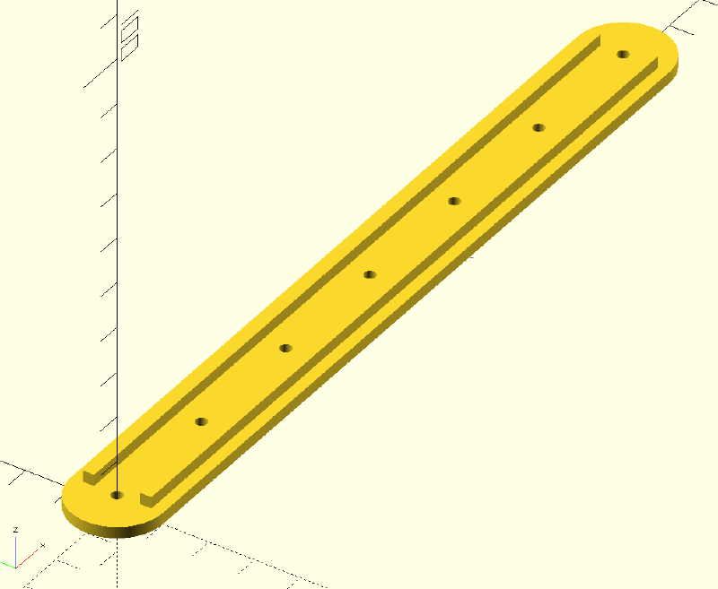
First steps were to measure the curve of the binnacle. 3D Printer to the rescue! My phone is about 165mm tall so I wrote this OpenSCAD code
length = 165;
width = 20;
num_points = 7;
$fn = 180;
height = 2.5;
linear_extrude(height = height)
{
    difference()
    {
        hull()
        {
            circle(d = width);
            translate([ length, 0, 0 ]) circle(d = width);
        }
        {
            for (i = [0:1:num_points - 1])
            {
                translate([ i * (length / (num_points - 1)), 0, 0 ]) circle(d = 2.5);
            }
        }
    }
}
translate([0,5,0]) cube([length,height,height*2]);
translate([0,-7.5,0]) cube([length,height,height*2]);
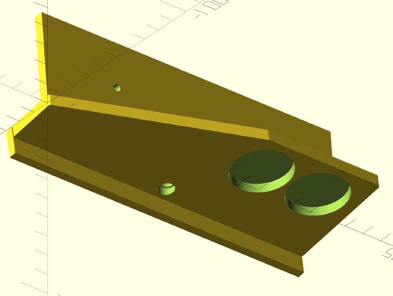
to produce this thing.
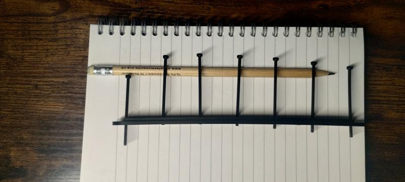
I could then wind in 7 2.5mm bolts and measure the curve.
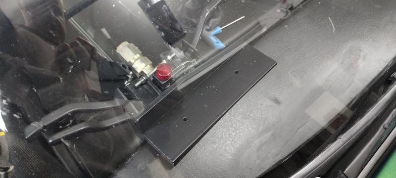
The leftmost one is deep as I was using it to measure a bolt offset (more on that later). Unfortunately, the part warped a bit, so I placed it on my desk and wound the bolts back to measure the curve and then added those to the first measurements.
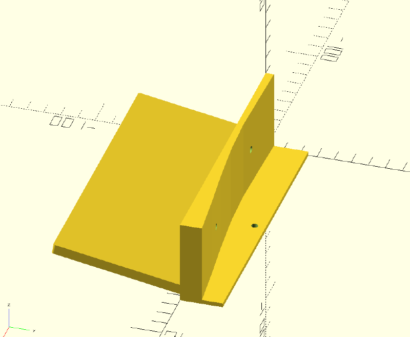
I then used those numbers in this code
distances = [ 1.75, 1.15, 0.6, 1.65, 4.1, 7.15, 9.75 ];
width = 165;
height = 75;
$fn = 180;
thickness = 3;
module dashInterface()
{
    difference()
    {
        linear_extrude(height = 50)
        {
            points = [for (i = [0:1:6])[(i * (width / 6)), distances[i] + 3]];
            poly = concat([[ 0, 0 ]], points, [[width, 0]]);
            polygon(points = poly);
        }
        translate([ 165 / 4, -10, 25 ]) rotate([ 270, 0, 0 ]) cylinder(d = 4, h = 50);
        translate([ 165 * 0.75, -10, 25 ]) rotate([ 270, 0, 0 ]) cylinder(d = 4, h = 50);
    }
    difference()
    {
        cube([ width, 25, 2.5 ]);

        translate([ width / 2, 3.6 + 15, -1 ]) cylinder(h = 10, r = 2);
    }
}
module phoneBack()
{
    difference()
    {
        linear_extrude(height = thickness * 2)
        {
            hull()
            {
                for (i = [
                         [ (thickness / 2), 0 ], [ width - (thickness / 2), 0 ], [ width - (thickness / 2), height ],
                         [ (thickness / 2), height ]
                     ])
                {
                    translate(i) circle(d = thickness);
                }
            }
        }
        #translate([ (165 - 37) + 20, height / 2, 1 ]) cylinder(d = 30, h = 30);
        #translate([ (165 - 37) - 20, height / 2, 1 ]) cylinder(d = 30, h = 30);
    }
}
translate([ 0, 1, 10 ]) rotate([ 170, 0, 0 ])
phoneBack();
dashInterface();
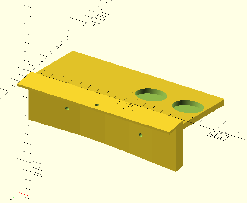
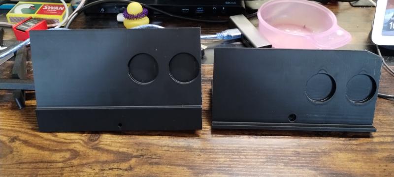
The offset I mentioned earlier was to locate the single 4mm hole in the front face. This lets me use one of the bolts that holds the dash top down as a locator. Failing that, I’ve got two other bolt holes I can use, but I’d rather not drill any holes if I can avoid it. The two large depressions are for some 30mm magnets to hold the phone in place.
I printed it, and found it was laughably too large. I hadn’t realised how low the windscreen is over the dashboard, so on to version 2.
Version 2 was better, it dropped the phone lower over the front of the dash, but it was still too big (you can see where I hacked the corner off it with a pair of cutters), and the 4mm hole was too precise. It needed some wiggle room to get everything lined up.
So on to version 3! I realised there was no need for the back to fully support the phone, so I cut that back and made the bolt hole 5mm.
distances = [ 1.75, 1.15, 0.6, 1.65, 4.1, 7.15, 9.75 ];
width = 165;
height = 55;
mag_height=37.5;
$fn = 180;
thickness = 3;
module dashInterface()
{
    difference()
    {
        linear_extrude(height = 50)
        {
            points = [for (i = [0:1:6])[(i * (width / 6)), distances[i] + 3]];
            poly = concat([[ 0, 0 ]], points, [[width, 0]]);
            polygon(points = poly);
        }
        translate([ 165 / 4, -10, 25 ]) rotate([ 270, 0, 0 ]) cylinder(d = 4, h = 50);
        translate([ 165 * 0.75, -10, 25 ]) rotate([ 270, 0, 0 ]) cylinder(d = 4, h = 50);
    }
    difference()
    {
        cube([ width, 25, 2.5 ]);
    }
}
module phoneBack()
{
    difference()
    {
        linear_extrude(height = thickness * 2)
        {
            hull()
            {
                for (i = [
                         [ (thickness / 2), 0 ], [ width - (thickness / 2), 0 ], [ width - (thickness / 2), height ],
                         [ (width - (thickness / 2))/2 +20, height ],[ (thickness / 2), height/2-3 ]
                     ])
                {
                    translate(i) circle(d = thickness);
                }
            }
        }
    }
    translate([ 0, -5, 0 ]) cube([ width, 4, 15 ]);
}

difference()
{
    union()
    {
        rotate([-5,0,0])dashInterface();
        translate([ 0, 25, 0 ]) rotate([ 170, 0, 0 ]) phoneBack();
    }

    translate([ 0, 25, 0 ]) rotate([ 170, 0, 0 ])
    {
        translate([ (165 - 37) + 16, mag_height, 1 ]) cylinder(d = 30, h = 30);
        translate([ (165 - 37) -16, mag_height, 1 ]) cylinder(d = 30, h = 30);
    }
    translate([ width / 2, 3.6 + 15, -10 ]) cylinder(h = 50, r = 3);
    translate([ width / 2, 3.6 + 15, -7 ]) cylinder(h = 5, r = 4);
}
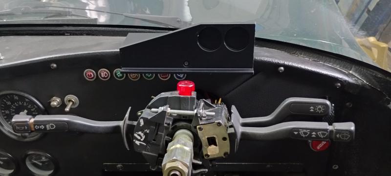
Which looks like this in the car. Just need the magnets to arrive and to re-route the USB cable from the ECU to use it effectively.
All in all, a fun day of fiddling which exercised my brain a little. I am finding OpenSCAD a little limiting/hard work. Over on locostbuilders.co.uk there is a thread that recommends TinkerCAD so I may have a play with that.
